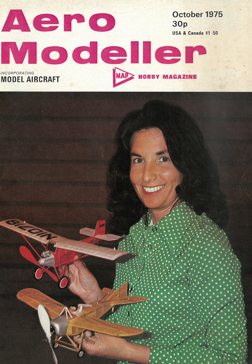
Aero Modeller old issue n°477 p.915 - October 1975
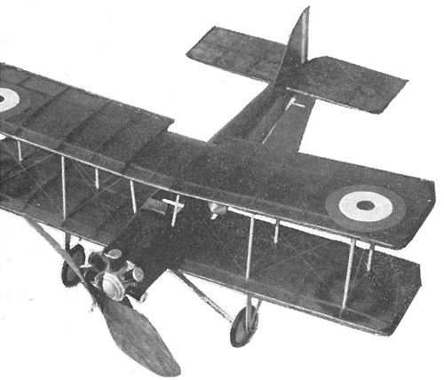
B.A.T. Baboon
It's peanut time again! an unusual prototype but with ideal proportion for indoor flying; unearthed by Walt Mooney. Full size plans overleaf.

HERE ARE MANY different reasons that one can have for selecting a Peanut Scale subject. Being limited to 13in. span, it is desirable to have relatively low aspect ratio wings, so as to result in the largest possible wing area. This airplane meets the low aspect ratio criteria, and has two wings! The design should have a fairly long tail moment — which this aircraft also has, while for good ROG take-offs it should have a stable landing gear arrangement. The Baboon has probably the widest track landing gear of any WW1 airplane. Some dihedral is also desirable.
Of course, the real reason a design is selected to model can be different from all of the above. In 1918 the British Aerial Transport Company constructed their Type FK24 ("FK" for Frederick Koolhoven) and gave it the name of "Baboon". What better reason to build a model than the fact that its name is unforgettable?
The prototype was intended as a very simple-to-build, easy-to-rig and simple-to-maintain trainer — this tends to make for a simple model and it is, with the exception of the dummy seven-cylinder engine. Thanks to the availability of Williams Brothers' plastic cylinders, even this problem is overcome.
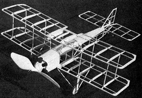
The fuselage is constructed by first making two side frames directly over the plan — these are shown hatched for clarity. The very first bay of the sides is filled with sheet balsa. When the cement is dry, remove the sides from the plans and separate the two side frames (if desired the frames can be built separately, but it is more accurate to build one on top of the other). Now cement the side frames together at the tail end. Set this above the top view of the fuselage so the correct angle of the sides at the tail post is obtained, and let it dry thoroughly. Then add the horizontal cross braces at each station, moving toward the nose. Note that the longerons will have to be cracked at the first station forward in order to give the sharp corner. Everywhere else the longerons will bend enough to take care of their change in direction.
When the basic box structure is complete, the top formers (A), through (F), can be added. Cut the "nose square" (A) and cement it into the nose of the box so it is just flush with the front end. Use soft, flexible Ain. sheet balsa to cover the upper deck of the fuselage, and carefully cut out the cockpit openings. Add 1/16 x 3/16 in. cross braces across the bottom of the box at positions in line with (B) and (B). These are cemented to the normal 1/16 in. square cross braces and to the uprights, and will provide some structure between the roots of the lower wings.
The tailplane and rudder are simple structures built directly over the plans, using 1/16 in. square sticks, and corner gussets cut out of 1/16 in. sheet balsa. Remove from the plans and carefully sand the outlines to a half-rounded section. Do not omit any of the gussets; they are essential to prevent covering wrinkles from occurring.
The wings are conventional structures, using notched ribs, leading and trailing edges and two top surface spars. The tip pieces are 1/8 in. square balsa. Again, remember the gussets. Cut four root ribs from 3/16 in. sheet (or cut twelve from 1/16 in. and laminate them three at a time to give the correct thickness). Cut out twenty-one of the regular ribs from 1/16 in. sheet.
Pin the leading and trailing edges to the plan. Cement the ribs in place. Cement in the tip structure and the gussets. Add the two spars. After the cement is dry in the rib notches, cut the spars to exactly fit at the tips and cement them in place. The spars should be flush with the top of the tips.
The lower wings end just at the inside of the root ribs —the top wing has a centre line rib. This is cut off even with the back of the aft spar and a triangular cross-section piece of balsa is used to fill in between the root ribs. The dihedral break for all wings is located at the outside of the thick root ribs. Carefully cut the outer panels free of the roots and reassemble the wings with 5/16 in. dihedral under each tip. Taper the ribs to give a good fit. When the cement is dry, sand the leading and trailing edges to the rounded and tapered cross-sections shown. Wing tips are also rounded.
Use lightweight tissue for covering all the components. To get an approximation of the right colour for the upper surfaces, I used "Brown" and "Olive Green" RIT dye dissolved in rubbing alcohol to dye a sheet of plain white tissue. To dye tissue, you first have to make a frame to hold the sheet that is to be dyed. Cement one together out of 1 x 1/4 in. or similar balsa, like a picture frame, and cement your sheet of tissue to it. Pull it as tight and smooth as possible, then spray the dye on to the tissue as evenly as you can. If you have no spray gun, it may be possible to dye the sheet using a cotton wad wet with dye, but much care will have to be exercised.
After the parts are covered, use a light fog of water to tighten the tissue. A single coat of clear dope (thinned about 50 per cent with thinner) was applied all over and then a second coat was applied to the fuselage. If you can get decals for the insignia, use them; if not available, then now is the time to paint on the roundels.
Assembly of the major components can proceed after the struts are made up. The struts are of round cross-section, not streamlined, and can be made from lengths of fin. diameter dowel. Drill a small hole through each end of the struts — this is used after assembly of the wings to facilitate the installation of the rigging. Cement the tail parts in place, then cement the lower wings to the fuselage sides. Make sure they are in the right place, and block up the tips to give the correct dihedral. Cement the four cabane struts in place on the top of the fuselage — a small hole will have to be cut into the top decking to accommodate each strut. Note that the rigging holes should be arranged to line up in a spar-wise direction. Carefully cement the top wing in place on the cabane struts — check their alignment.
When the cement holding the struts in place is dry, install the rigging, using 2lb. BS monofiliment fishing line — drafting tape is handy to hold the loose ends as the rigging is threaded through the holes. When all the rigging is in place, check the wing alignment, then put a small drop of cement at each of the strut holes to hold the rigging permanently. Trim off all the excess ends. Now cut the tail skid and the two main landing gear legs out of bin. ply and bend the main gear axle.Cover the inverted "V" portion of the wire with 1/32 in. diameter tubing to give the axle the right diameter. Cement the wire in place in the bottom of the fuselage —adding a filler to the bottom of the first bay of the fuselage to reinforce it. Cement the tailskid in place. Slip a wheel over each end of the axle wire and cement the gear legs in place on the bottom of the lower wings. A washer and a drop of cement retains the end of the axle in the leg.
Now for the dummy engine. The crankcase is a piece of block balsa with the grain parallel to the airplane centre line — use the front view to get the seven sides accurately carved. Cut the square hole to fit the thrust bearing. Install the cylinders by making a hole to fit the base of each cylinder exactly in the centre of the seven faces, then add a circular balsa cylinder head to each one, and use cut-off straight pins to simulate the pushrods.
The fuel tank is wrapped from three pieces of bond paper — the ends can be carved from block balsa and the centres can be wrapped out of bond paper. Paint in silver, and cement in place on the wing.
Before flying your model, make sure it balances somewhere near the CG shown. Look at the wings and make sure that you have about washout at each tip. This can be incorporated by holding the wings in the correct position and holding the airplane over a source of heat which will shrink the loose wires and hold the wing permanently twisted with the correct washout. Too much heat will break the wires, so hold a bare hand between the heat source and the model. When it hurts, remove everything from the heat source!
This model is a rather large, draggy model for a Peanut Scale, and requires a bit more rubber to fly than you might expect — the original was powered just about right for outdoor flying with a single loop of 3/16 in. Pirelli approximately 12in. long.