Model Builder old issue vol. 22 N°7 p.43-46 - April 1973 - Walt Mooney
Steve Wittman's VW Racer
To anyone who has even the slightest interest in aviation, Steve Wittman needs no introduction. This racing pilot from Oshkosh, Wisconsin has been building winning racers for more than 40 years, and is still piloting them in races wherever a race is promoted. His designs are famous for being light, simple and fast. They are also famous because they do not follow the "French curve" smoothness approach to aerodynamic efficiency. Thus, his airplanes have not always looked fast, but they have always been fast.

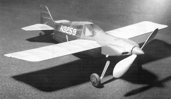
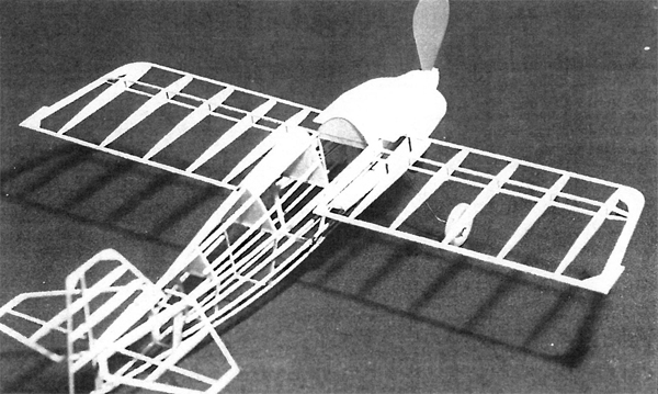
This VW-powered racer is in Wittman's best tradition. It is a boxy, angular airplane. By using wire bracing, the wing can be made much lighter and thinner. Keeping a racer as light as possible is important, because a considerable portion of the drag of any airplane is induced by the amount of lift developed to hold the airplane up. The lower the weight, the more quickly the airplane will accelerate, both on the initial takeoff and after each pylon turn. There are two intentional deviations from scale in the model; the area of the horizontal tail has been increased slightly, and the dihedral has been increased from nothing to 1/8-inch. The wing has been designed to use wire bracing just like the full-size racer. Note that the top longerons are spread wider apart than the bottom longerons. Thus, the wing contacts the fuselage structure only along the upper longeron. Without the wire bracing (nnonofilament fishing line), the wing attachment would be somewhat fragile. Although this method adds some complexity to the usual approach of just cementing the root rib to a flat fuselage side, it offers the ad-vantage of being able to adjust the dihedral by rerigging the bracing — a simple job with monofilament, which can be shrunk with the application of a little heat.


If most of your Peanut flying is done outdoors, I'd recommend following the wood sizes called out on the plan. The model in the pictures, however, was built with 1/20 square instead of 1/16, and 1/20 sheet instead of 1/16 sheet. This results in a considerable reduction in weight. This special size wood is available by mail from Peck-Polymers, P.O. Box 710399-MB, Santee, CA 92072. For more information, send $3.00 for their complete catalog.
Peck Polymers - Wind-it-up
The structure on this model is fairly standard, but there are subtle differences that warrant special discussion. The airfoil section of the wing is not flat-bottomed. I chose to use a scale-like (semi-symmetrical) airfoil that has a very small pitching moment. When the wing is built over the plans, the trailing edge must be supported above the plan by about 1/16-inch.
The fuselage basic structure consists of two sides built over the plan, removed from the plan, cemented together at the tail post, and then separated from each other by a series of cross pieces at the location of each upright, to make a common box structure. It's important to note, however, that this fuselage box is not rectangular in cross-section, but trapezoidal. That is, the upper longerons are farther apart than the lower ones. Care is required in making this basic assembly. Because of the difference in width, fuselage sides that are assembled over the plan will curve upwards at the tail, re-sulting in a little nose-up adjustment of the tail. This happened in the case of the model in the photos, and was left that way with no noticeable change in the shape. If you want to compensate for this, you can, during assembly of the sides over the plans, shift the longerons at the tailpost downwards 1/16 of an inch.
The nose contours, except at the very front, are angular and generally straight-lined. Therefore, on this model, the cowl has been built up of sheet balsa; 1/16 sheet was used between the first two fuselage stations, and 1/32 sheet was used from there aft. The cross-section of the nose block requires that you fill the inside corners of the forward part of the cowling with 1/4-inch square triangular stock so that the very front of the cowling just aft of the nose block can be carved to the rounded shape of the noseblock.
The landing gear wire comes out of the fuselage about 3/16 of an inch up from the bottom. To install it, cut a narrow notch in the lower structure and then fill the notch after cementing the wire in place.
The vertical tail is an integral part of the fuselage structure. The top center stringer cements to the vertical tail leading edge and a small sheet balsa fillet makes the curved fairing between the stringer and the fin. Fuselage and fin covering is continuous. This means that the horizontal tail must be covered and installed before the vertical tail can be installed and the top of the fuselage covered.
My propeller spinner was carved from block balsa and hollowed out. It was then epoxied to a Peck-Polymers 4-3/4 inch diameter plastic propeller, aften installing the prop hook. Usually I put a winding loop on the front of the prop, but I felt this would louse up the looks of the spinner, so for mechanical winding, the noseblock must be removed and the rubber disconnected from the prop hook. This is a little less convenient, but I've seen a lot of photos of modelers holding propellers in their mouths while winding, so I do it too, while winding this one!
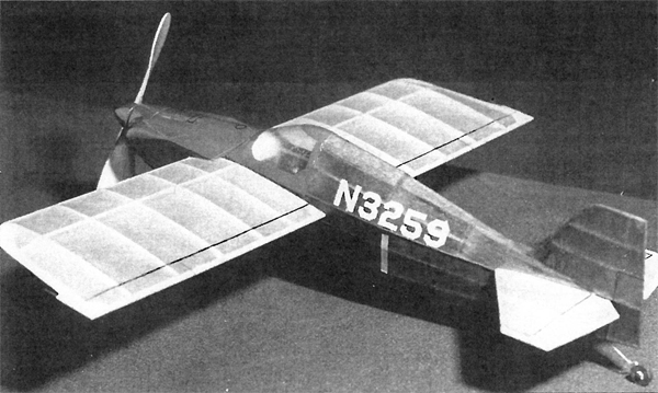
Wittman's color scheme is green on the fuselage and vertical tail, with yellow wings, horizontal tail and trim. The correct numbers show in the photos.
Download the plan (Walt Mooney).